Wall Installation
Read before installation
Before beginning the installation, read this documentation carefully and completely. Failure to follow the recommended procedures may result in serious injury, death, property damage, or violation of local electrical regulations.
PG LAB Electronics is not responsible for any loss or damage resulting from incorrect installation or operation of this device.
High voltage – qualified personnel only
Installation of the E-VLXESP32 involves high AC voltages and must be carried out by a qualified electrician. There is a serious risk of electrocution.
Warning
Connect the E-VLXESP32 only as shown in these instructions. Any other wiring method may cause damage or injury.
Warning
Any changes to wiring connected to the screw terminals must be performed only after all local power sources have been switched off and disconnected.
Warning
The VELUX® front cover must be removed or attached only when all power sources are disconnected.
Warning
Do not install the E-VLXESP32 where it may get wet, exposed to direct sunlight, or near sources of heat.
Warning
Do not use the E-VLXESP32 if it has been damaged. Do not attempt to service or repair the device yourself.
Basic wiring diagram
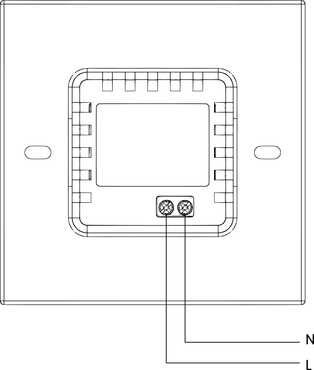
The following image shows the power line wiring connections.
 }{: .center
Fig. 1 – Wiring to power line
| Terminal | Wire |
|---|---|
| N | Neutral |
| L | Live (100–240 V~, 50/60 Hz) |
Installation
Important
Ensure that the VELUX® wall remote control has been prepared as described in the
Preparation section before continuing.
Before starting the installation, verify that the circuit breakers are switched off and that no voltage is present on the power lines. Use a phase tester or multimeter to confirm this (Fig. 2).
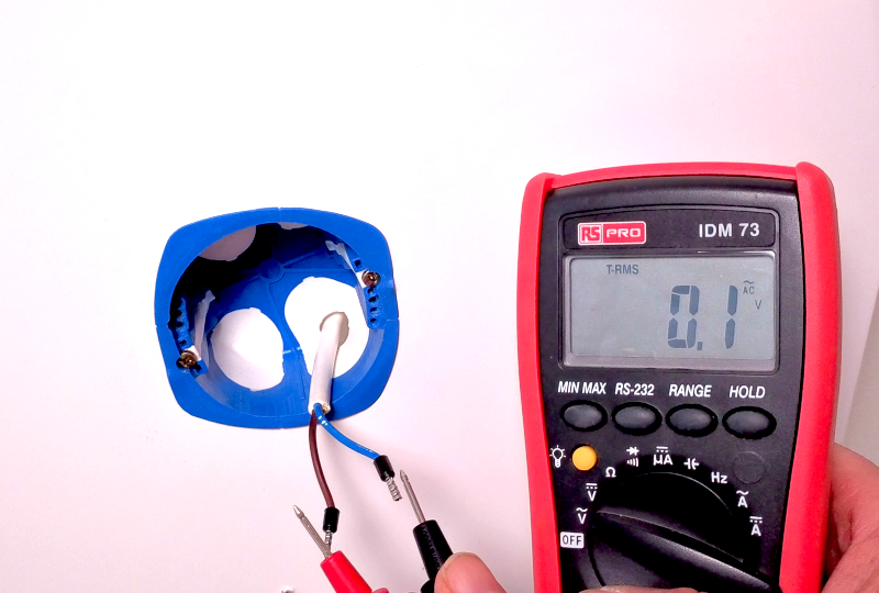
Fig. 2 – No voltage on the power line
Connect the wires to the E-VLXESP32 according to the wiring diagram (Fig. 1).
- Connect the Live wire to terminal L
- Connect the Neutral wire to terminal N
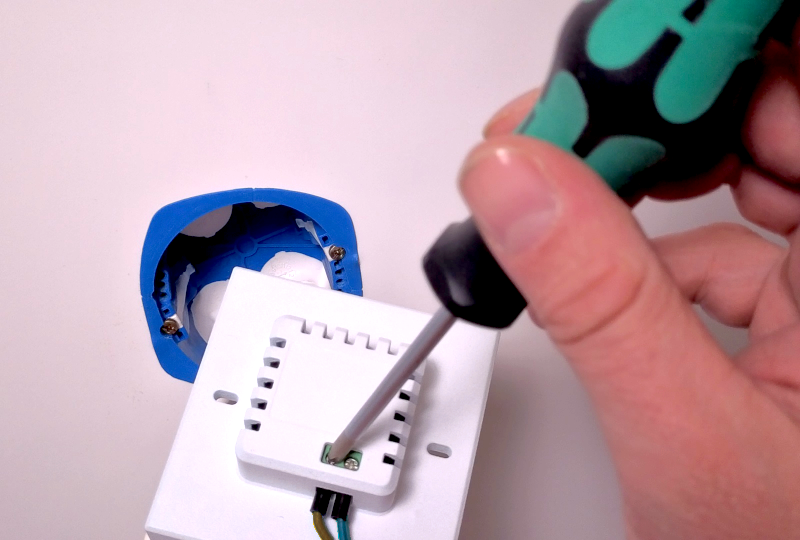
Fig. 3 – Connecting the wires
Insert the E-VLXESP32 into the wall box and secure it using the two screws supplied with the box.
Warning
Do not overtighten the screws, as this may damage the plastic enclosure.
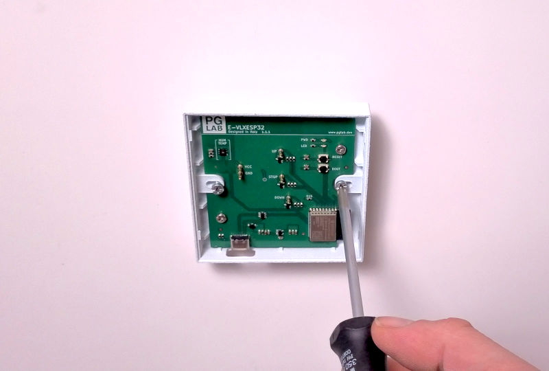
Fig. 4 – Wall insertion
Attach the VELUX® wall remote control cover by pressing it onto the E-VLXESP32 until you hear a click.
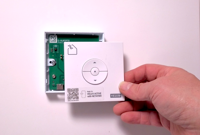
Fig. 5 – Attaching the cover
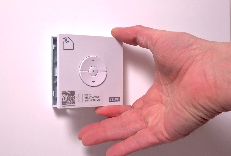
Fig. 6 – Snap-fit click
Caution
Be very careful not to bend the E-VLXESP32 pogo pins when inserting the VELUX® wall remote control cover.
Completion
Congratulations! Your E-VLXESP32 is now installed.
You may now restore power by turning the circuit breakers back on.
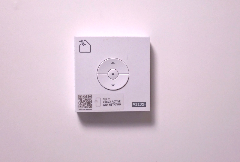
Fig. 7 – Installation complete