E-VLXESP32 - Kit Version
Specification
The following table shows the general specifications of the E-VLXESP32.
| Feature | Details |
|---|---|
| MPU | ESP32-C3 |
| Flash Memory | 4 MB |
| Circuit Operating Voltage | 3.3 V |
| Communication | Wi-Fi 802.11 b/g/n 2.4 GHz |
| Ambient Sensor | HDC1080 |
| Protection | ESD protection on USB-C port |
| Protection Rating | IP20 |
| Certifications | CE, RoHS |
Electrical Information
| Parameter | Details |
|---|---|
| Standard Input Voltage | 5 VDC |
| Power Consumption | 50 mA |
| Power Supply | From USB-C port |
| Protection | Transient protected |
Functional Overview
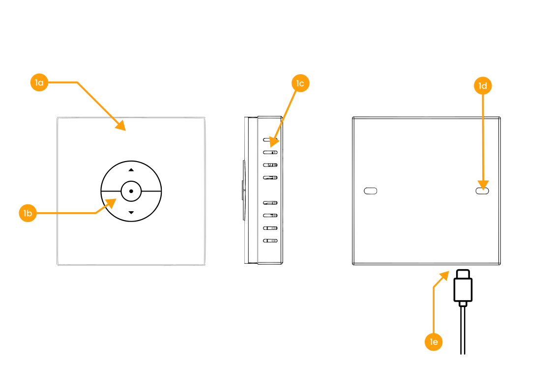
E-VLXESP32 views.
| Ref. | Description |
|---|---|
| 1a | VELUX® remote cover (*) |
| 1b | Control buttons |
| 1c | Ventilation grid |
| 1d | Mounting holes |
| 1e | USB-C port. |
(*) The VELUX® remote cover is not included with the E-VLXESP32 and must be provided by the customer.
The plastic enclosure of the device must be 3D print.
Mechanical Information
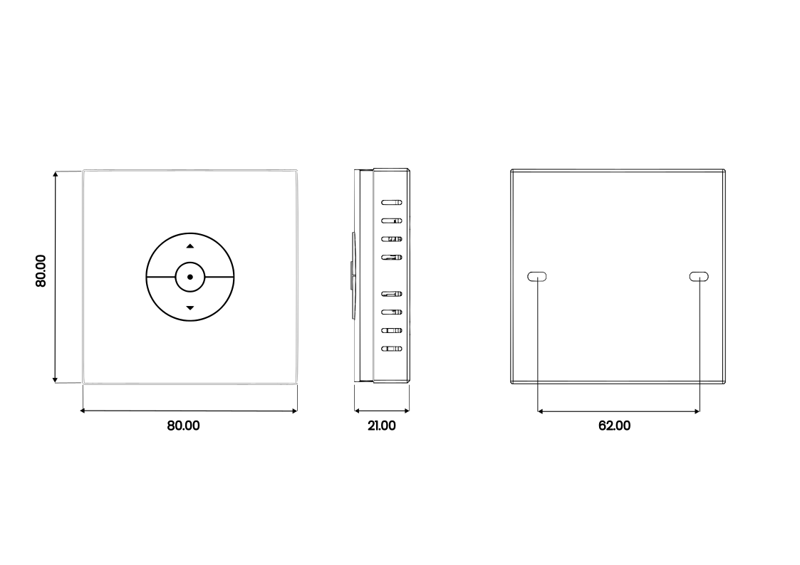
E-VLXESP32 kit outline (dimensions in mm).
| Description | Value |
|---|---|
| Width | 80 mm |
| Height | 80 mm |
| Depth | 39 mm |
| Weight | 80 g |
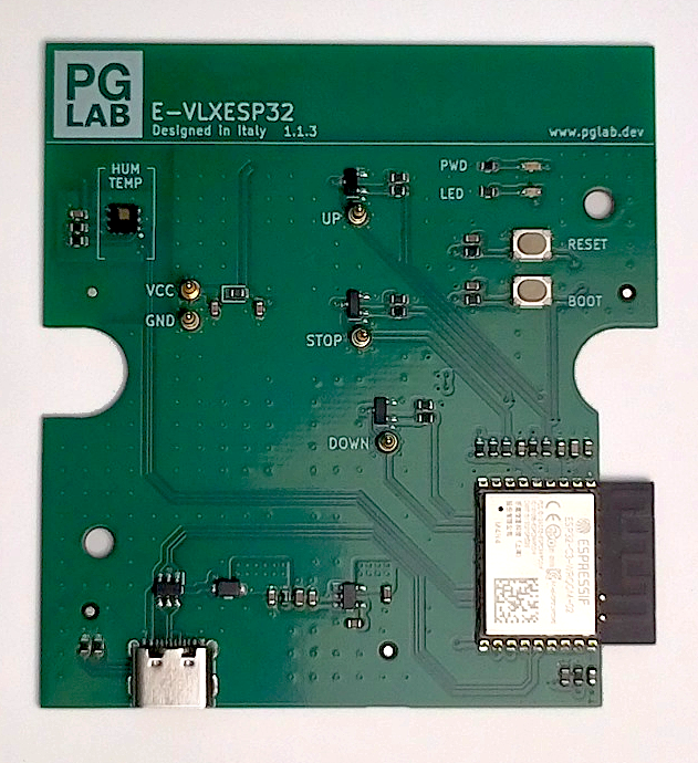
Board Topology
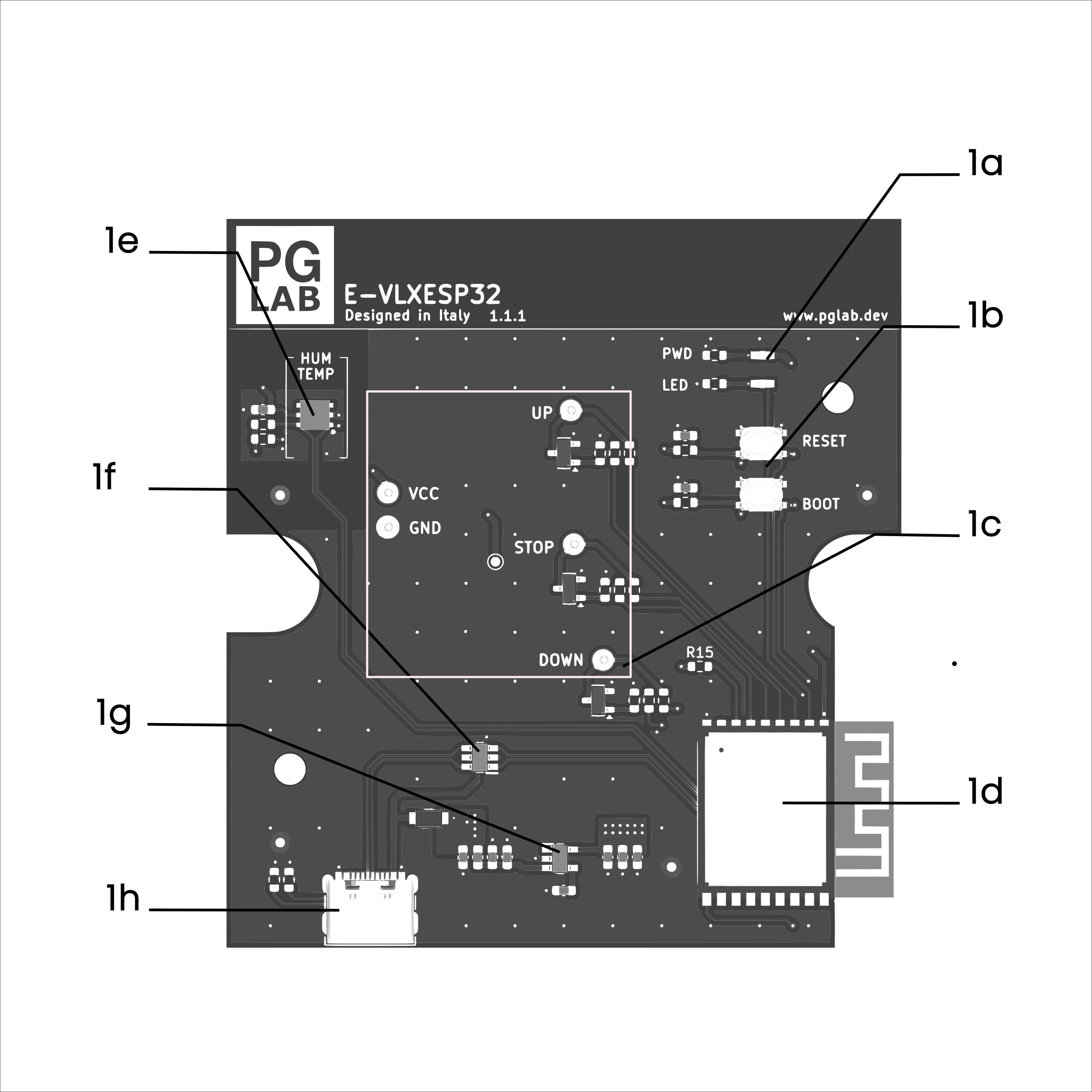
E-VLXESP32 Circuit Top View
| Ref. | Name | Description |
|---|---|---|
| 1a | LEDs | Power LED (red), User LED (green) |
| 1b | Buttons | Tactile switches for reset and bootloader mode |
| 1c | Pogo Pins | Gold-plated pins for solderless connection to VELUX® remote |
| 1d | ESP32-C3 | Single-core Wi-Fi module |
| 1e | HDC1080 | High-accuracy digital temperature and humidity sensor |
| 1f | ESD | Data line ESD protection |
| 1g | LDO | Low-noise voltage regulator |
| 1h | USB-C | Flashing firmware and powering the board |
GPIO Pinout
| Pin | Function. |
|---|---|
| GPIO3 | I2C SDA |
| GPIO2 | I2C SCL |
| GPIO1 | POGO PIN DOWN (shutter) |
| GPIO7 | POGO PIN STOP (shutter) |
| GPIO5 | POGO PIN UP (shutter) |
| GPI10 | POGO PIN UP (binary sensor) |
| GPIO6 | POGO PIN STOP (binary sensor) |
| GPIO0 | POGO PIN DOWN (binary sensor) |
Wiring Diagram
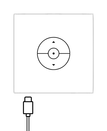
E-VLXESP32 kit connect to the USB power cable
Setup and Use
Read before installation
Before beginning installation, read this documentation carefully and completely.
Failure to follow recommended procedures may result in device malfunction, serious injury, or violation of local electrical regulations.
Handling
- Connect the E-VLXESP32 only as shown in these instructions.
- Ensure all power sources are disconnected before any wiring changes.
- Do not remove or attach the VELUX® front cover while power is connected.
- Do not use the device if it has been damaged.
- Do not attempt to repair or service the device yourself.
- Keep the device away from children.
Environment
Do not install the device where it may get wet, in direct sunlight, or near heat sources.
Certification
PG LAB Electronics S.R.L.S declares, under sole responsibility, that E-VLXESP32 complies with the following EU Directives and therefore qualifies/qualify for free movement within markets comprising the European Union (EU) and European Economic Area (EEA).
RoHS Directive 2011/65/EU:
- EN IEC 62311:2020
Directive 2014/30/UE (EMC):
- EN IEC 63044-5-1:2019/A1:2024
- EN IEC 63044-5-2:2019/A1:2024
Radio Equipment Directive (RED) 2014/53/UE:
EMC (RED Article 3.1b):
- EN 301 489-1 V2.2.3:2019
- EN 300 328 V2.2.2:2019
Disclaimer
Important
The E-VLXESP32 is an independent third-party product developed and manufactured by PG LAB Electronics S.R.L.S. It is not affiliated with, endorsed by, or sponsored by VELUX A/S or any of its subsidiaries or affiliates.
VELUX® is a registered trademark of its respective owner. All references to VELUX® products, including compatible remote control models, are made solely for the purpose of indicating compatibility.